Landing a Quadrotor on a Moving Robot
A 50 Hz convex MPC, OptiTrack feedback, and a Crazyflie 2.1 catching up to a moving ground robot before settling onto a landing pad on its roof.
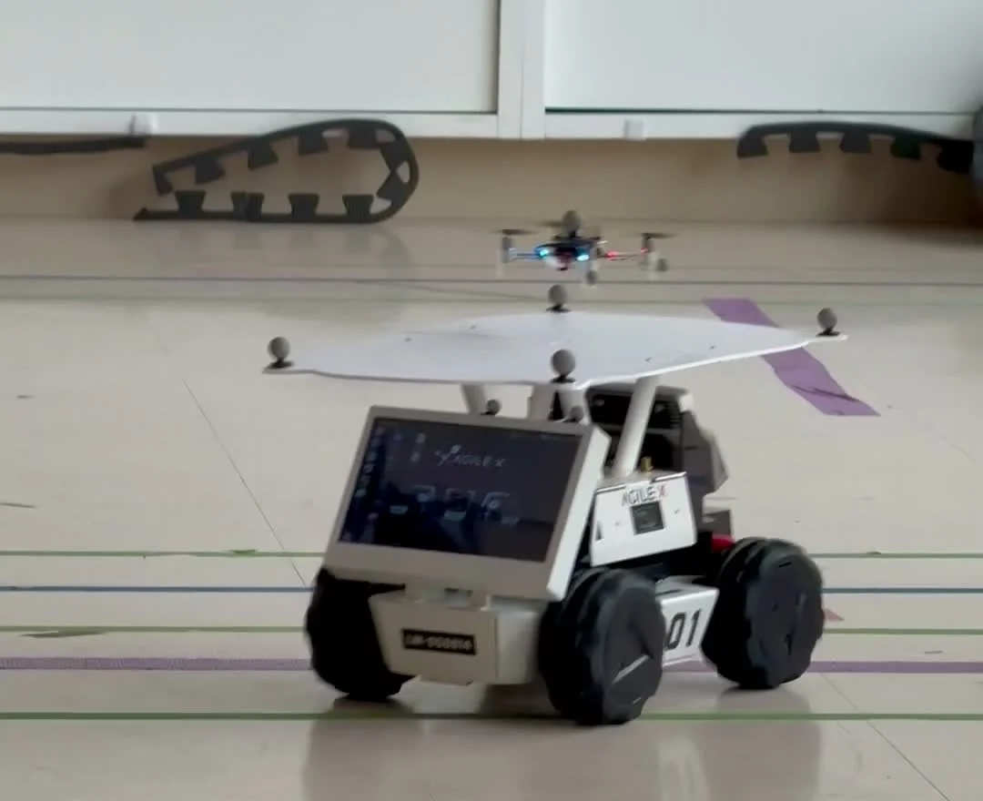
Crazyflie 2.1 closing the lateral gap before descending onto the AgileX LIMO's rooftop landing pad. RASTIC mocap arena at BU.
Most papers on autonomous drone landing assume the landing zone holds still. Pick the platform up — drive it forward, drive it in a circle, swerve it back and forth — and the problem changes. The drone has to predict where the platform will be by the time it arrives, hold position above a moving target, and descend without slamming into it. We built a system that does this for the ME701 Optimal Control class at BU, with two teammates, Benjamin Hsu and Yancheng Zhou. A Crazyflie 2.1 quadrotor flies on stock firmware in the RASTIC motion-capture arena; an AgileX LIMO ground robot drives the landing platform around. A laptop in the loop solves a convex quadratic program at 50 Hz and tells the drone how to tilt and how hard to push.
We tested the closed loop across four ascending platform-motion regimes — stationary, straight-line, circular, and erratic teleoperated motion. The drone landed in all four. Lateral tracking error grew steadily with the chaos, from ten centimeters in the stationary case to nearly a meter in the erratic one. Altitude error stayed in a five-centimeter band across all four. The page below is the why behind those numbers.
Why a linear MPC
A quadrotor is a nonlinear plant — six rigid-body states, four inputs, gravity coupled into orientation. Nonlinear MPC is solvable on modern hardware in real time, but it is heavy to set up and tune for a course project, and our flight envelope is slow. No aerobatics, no aggressive descent, no high-tilt regimes. A linear formulation is enough.
We split the controller into the standard cascade. The Crazyflie's onboard attitude loop closes much faster than our outer loop, so from the outer loop's perspective, commanded tilts are realized nearly instantly and the only control authority is the resulting body-frame acceleration. The translational dynamics in the world frame then reduce to a 3D double integrator with gravity entering as a constant affine term. The hover input cancels gravity in the cost so steady hover incurs no control effort. The small-angle approximation that maps acceleration back to roll, pitch, and thrust on the way out introduces a residual on the order of α³/6 — under our 15° tilt cap, that is about 0.3% of g. Smaller than any of the unmodeled effects we actually had to compensate for.
Each step of the loop becomes a convex QP with a horizon of fifty steps (one second), solved with CVXPY and OSQP. At 50 Hz the solver finishes well within the control period and we apply only the first input.
Offset-free, because the battery sags
The double integrator alone is not enough on a Crazyflie. The drone discharges fast and visibly. As the battery drops, thrust per PWM unit drops with it. Without compensation the drone sinks below its altitude setpoint within a minute and stays there. The controller is doing its job; the model is lying about how much lift it gets per unit input.
The standard fix is offset-free MPC. We augment the state with a single scalar, d, that enters the dynamics as an additive vertical-acceleration bias and evolves trivially as d[t+1] = d[t]. The augmented state has seven entries — three position, three velocity, one disturbance. At every tick, d is updated outside the optimization from the prediction residual on vertical velocity. Battery sag, prop wear, downwash near the pad, mass changes from added markers and tape — anything that contributes a roughly-constant vertical bias collapses into one scalar, and the MPC's reference tracking absorbs it at steady state. After this change the drone holds altitude for the duration of a battery without slowly sinking.
This piece is the strongest classical-control idea in the system. Linear MPC is the textbook part. The disturbance state is the part that makes it actually work on hardware that drifts.
Where the platform will be
The MPC's outer-loop horizon is one second. If we give it a static reference — wherever the LIMO is right now, projected forward as a constant — and the LIMO drives in a circle, the reference systematically lags the platform's actual trajectory and the drone perpetually chases. The MPC is doing the right thing for the reference it sees; the reference is lying.
We feed it a constant-turn-rate, constant-velocity (CTRV) prediction of the platform's xz trajectory instead. Given the LIMO's current velocity and yaw rate from its own OptiTrack stream, the predicted path over the next second is closed-form — the position integrates analytically to a function of sin ωt and 1 − cos ωt — and degenerates gracefully to constant-velocity extrapolation when |ω| is small. This lets the MPC preview the lateral acceleration it will need to stay centered as the platform turns, instead of always playing catch-up.
The reference for tracking is then the predicted platform trajectory, vertically offset by half a meter so the drone hovers above the pad. The MPC sees a moving target, not a frozen waypoint.
Cone-gated descent
For descent, the obvious thing is to lower the altitude reference at a constant rate while keeping the lateral reference centered on the platform. The obvious thing has a problem. If the drone has not actually closed the lateral gap before descent begins, the optimizer is asked to minimize altitude error and lateral error at once, and the descent ramp eats budget that should be going into lateral closure first.
The fix is to gate the altitude reference on a cone. The pad sits at the apex of a 20° cone opening upward, with a five-centimeter base disk. Whenever the drone is inside that cone, the altitude reference descends as planned. Whenever it is outside, the altitude reference freezes at the drone's current altitude. The controller then sees zero altitude error and spends all of its control authority closing the lateral gap. Once the drone re-enters the cone, the descent ramp resumes.
This is a state machine implemented as a reference design rather than a mode switch in the controller. The MPC core never knows about modes. It just tracks whatever reference the guidance layer hands it. That separation made the mode logic easy to reason about and easy to change. Touchdown is detected one step outside the MPC, when altitude is within five centimeters of the pad and the drone is inside the cone — at which point the motors cut.
A separate proportional yaw controller runs alongside the position MPC, slaving the drone's heading to the platform's so the small-angle linearization stays accurate. A boundary supervisor in front of the radio disarms the motors on arena violation or on more than two seconds of pose-stream loss. Every flight writes a per-tick CSV, an infeasibility log, and an event log — every flight is replayable.
Four experiments
We ran four hardware experiments, all sharing the same takeoff–hover–tracking–descent sequence and differing only in how the LIMO moved underneath.
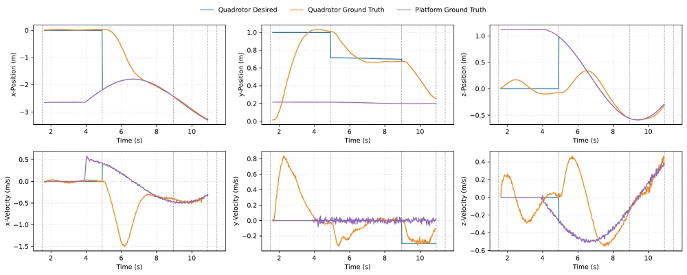
In the stationary case the LIMO sits still. The drone holds position with millimeter-scale oscillations and follows the descent ramp almost exactly. Lateral RMS error is about ten centimeters, dominated by the tracking-entry transient. With the LIMO driving in a straight line at constant speed, the drone is starting two meters behind the platform when tracking engages and has to chase before the descent ramp begins. With the LIMO driving in a circle, the drone tracks the curving xz trajectory with visible phase lag in z but matching amplitude — the CTRV prediction earns its keep here. With the LIMO teleoperated to swing back and forth unpredictably, the drone follows the zig-zag with a fraction-of-a-second delay, since the predictor cannot anticipate reversals it has no model of. The tracking-entry burst is the largest of the four cases here.
The drone lands in all four.
| Experiment | x (m) | y (m) | z (m) | Yaw (°) |
|---|---|---|---|---|
| Stationary | 0.10 | 0.24 | 0.08 | 7.6 |
| Straight-line | 0.65 | 0.29 | 0.37 | 3.1 |
| Circular (CCW) | 0.68 | 0.28 | 0.29 | 15.4 |
| Erratic teleop | 0.95 | 0.25 | 0.34 | 25.6 |
The interesting row of that table is not the lateral one — it is the altitude. It stays in a 24–29 cm band across all four scenarios, even as the platform's motion gets unpredictable. That is the offset-free disturbance estimator and the cone gate working as designed. The lateral controller is allowed to struggle; the altitude is held.
Where it breaks
Erratic teleop is also where the system reveals its limits. Three simplifications stack up underneath the controller. The CTRV predictor extrapolates the platform's current turn rate forward, so reversals are out of model. The small-angle approximation in the acceleration-to-attitude mapping is good only while peak tilt stays well under the 15° cap. The 2 m/s velocity bound caps how fast the drone can catch up to a maneuver. Erratic motion that stays inside that envelope is fine. Faster reversals, or larger-amplitude swings, would break it.
This is the part of the writeup I find most useful to share. Every controller has an envelope where its assumptions hold, and the work of reporting results is the work of finding where the envelope ends.
What's next
A few things worth changing. The reference trajectory currently steps at each mode change — hover to tracking, tracking to descent — which gives the MPC a discontinuity to chase; blending the reference between modes would smooth the transients. Swapping the linear MPC for a nonlinear formulation would let the system fly a five-inch quadrotor at outdoor speeds onto something like the back of a moving truck — small-tilt no longer holds at those speeds. And replacing OptiTrack with onboard visual-inertial odometry would unbind the system from the arena.
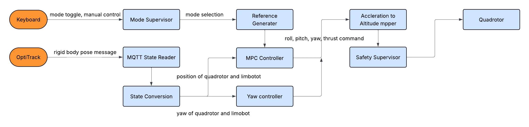
The architecture is summarized below.
Course project for ME701 Optimal Control, BU Spring 2026, with Benjamin Hsu and Yancheng Zhou.